Low battery
Battery level is below 20%. Connect charger soon.


12 Volt Wiring Diagram – Complete Beginner’s Guide to Get It Right
So, you’re diving into the world of 12-volt wiring? Whether you’re working on a car, a boat, an RV, or even a small DIY project, understanding how to read and use a 12-volt wiring diagram is crucial for a safe and successful outcome. This guide is designed specifically for beginners, breaking down the complexities into easily digestible chunks. We’ll cover everything from the basics of reading a diagram to the essential safety precautions you need to take. Let’s get started and ensure your project is wired correctly!
What is a 12-Volt Wiring Diagram?
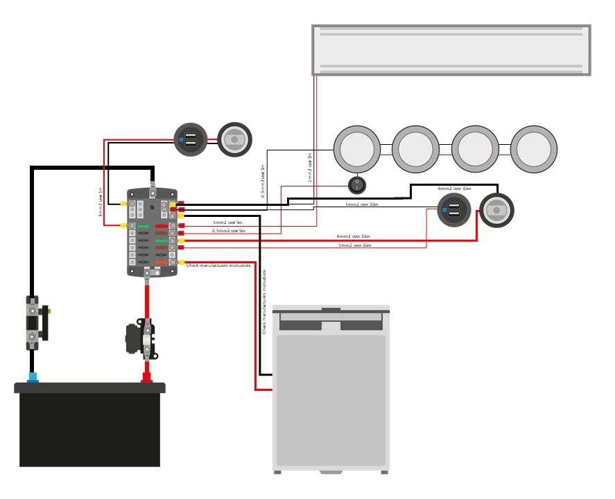
A 12-volt wiring diagram is a visual representation of the electrical circuits within a 12-volt system. It acts as a roadmap, showing how different components (like batteries, lights, switches, and fuses) are connected and how electricity flows through them. Instead of relying on guesswork, a wiring diagram provides clarity and helps you:
- Troubleshoot Problems: Quickly identify the source of electrical issues.
- Make Modifications: Safely add or remove components from your system.
- Understand the System: Gain a comprehensive understanding of how your electrical system works.
- Prevent Damage: Avoid short circuits and other electrical hazards.
Decoding the Language of a 12-Volt Wiring Diagram
Wiring diagrams use a standardized set of symbols and conventions. Understanding these is key to deciphering the diagram’s meaning. Let’s break down the most common symbols:
- Power Source (Battery): Represented by a circle with a “+” (positive) and “-” (negative) symbol inside.
- Ground: Often depicted as a series of horizontal lines decreasing in length, connected to a point. This represents the connection to the vehicle’s chassis or a common ground point.
- Wire: Lines connecting the components, often color-coded to indicate their function.
- Switches: Various symbols representing different types of switches (e.g., on/off, momentary).
- Lights: Represented by a small light bulb icon.
- Fuses: Squares or rectangles, often with a rating (e.g., 10A) to indicate the current capacity.
- Resistors: Zigzag lines, used to limit current flow.
- Connectors: Circles or squares with lines to show where wires connect.
- Relays: Rectangles with internal symbols to represent their function, used to control high-current circuits with low-current signals.
Understanding the Components of a 12-Volt System
Before diving into the diagram, it’s important to know the basic components of a 12-volt system:
- Battery: The power source, providing 12 volts of direct current (DC).
- Fuses: Protective devices that break the circuit if the current exceeds a safe level, preventing damage to components and wiring.
- Wiring: Conductors that carry the electrical current, typically made of copper.
- Switches: Devices that control the flow of electricity, allowing you to turn components on and off.
- Lights & Other Loads: Devices that consume electrical power, such as headlights, tail lights, and accessories.
- Ground: The return path for the electrical current, completing the circuit.
Essential Steps for Reading and Using a 12-Volt Wiring Diagram
Here’s a step-by-step guide to help you navigate a 12-volt wiring diagram:
- Identify the Power Source: Locate the battery symbol and identify the positive (+) and negative (-) terminals.
- Trace the Positive Path: Follow the wires from the positive terminal through fuses, switches, and to the load (e.g., light).
- Identify Fuses and Relays: Note the fuse ratings and the function of any relays in the circuit.
- Follow the Ground Path: Trace the wires from the load back to the ground. This completes the electrical circuit.
- Color Coding: Pay attention to the wire colors, as they often indicate the function of the wire.
- Component Identification: Identify all components and their connections.
- Troubleshooting: If you’re troubleshooting, use the diagram to isolate the problem by checking voltage at different points in the circuit.
Safety First: Precautions to Take
Working with electricity requires careful attention to safety. Always remember these crucial safety tips:
- Disconnect the Negative Terminal: Before starting any work, disconnect the negative (-) terminal of the battery to prevent accidental shorts.
- Wear Safety Glasses: Protect your eyes from sparks and debris.
- Use Insulated Tools: Use tools with insulated handles to prevent electrical shock.
- Double-Check Connections: Ensure all connections are secure and properly insulated.
- Check for Shorts: Before applying power, double-check your wiring for any potential short circuits.
- Work in a Well-Ventilated Area: If working with batteries, ensure adequate ventilation to avoid inhaling fumes.
- Use a Multimeter: A multimeter can help you check for voltage, continuity, and shorts.
Common Mistakes to Avoid
- Incorrect Wire Connections: Always double-check your wiring connections against the diagram.
- Using Incorrect Fuse Ratings: Using a fuse with a rating too high can lead to component damage and fire.
- Overloading Circuits: Exceeding the current capacity of a circuit can cause overheating and damage.
- Poor Ground Connections: A bad ground connection can lead to electrical problems.
- Ignoring Safety Precautions: Always prioritize safety when working with electricity.
Conclusion: Mastering 12-Volt Wiring
Understanding 12-volt wiring diagrams is a valuable skill for anyone working on electrical projects. By learning the symbols, understanding the components, and following the steps outlined in this guide, you can confidently navigate these diagrams and wire your projects safely and effectively. Remember to prioritize safety and always double-check your work. Happy wiring!
FAQs – Frequently Asked Questions
1. Where can I find a 12-volt wiring diagram for my vehicle/project?
You can often find wiring diagrams in the vehicle’s service manual, online forums dedicated to your vehicle or project, and specialized wiring diagram websites. Make sure the diagram is specific to your model year and any modifications you’ve made.
2. What size wire should I use?
The wire size (gauge) depends on the current draw of the component you’re wiring. Consult the wiring diagram or a wire gauge chart to determine the appropriate wire size for your application. Thicker wires (lower gauge numbers) can handle more current.
3. What is a multimeter, and how do I use it?
A multimeter is a versatile tool used to measure voltage, current, and resistance. To use it, select the appropriate setting (e.g., voltage, ohms) and connect the probes to the circuit or component you want to test. Consult a multimeter tutorial for detailed instructions.
4. Why is a good ground connection so important?
A good ground connection provides a low-resistance return path for the electrical current. A poor ground connection can lead to dim lights, intermittent operation, and other electrical problems. Ensure your ground connections are clean, tight, and connected to a solid metal surface.
