Low battery
Battery level is below 20%. Connect charger soon.


3-Way Switch Electrical Diagrams – Step-by-Step Wiring Made Simple
Have you ever walked into a room and wished you could turn on the lights from both ends? That’s the magic of a 3-way switch! Understanding how to wire these switches can dramatically improve your home’s functionality and convenience. This article will provide a clear, step-by-step guide to understanding and successfully wiring 3-way switches, demystifying the electrical diagrams and making the process accessible, even for beginners.
Understanding the Basics of 3-Way Switches
Before diving into the diagrams, it’s crucial to grasp the fundamental concept. Unlike a standard on/off switch, a 3-way switch doesn’t simply open or close a circuit. Instead, it diverts the flow of electricity. It has three terminals:
- Common Terminal (COM): Usually a darker color (often black or brass) and often identified by a screw color. This is where the power source (hot wire) or the light fixture wire (load wire) connects.
- Traveler Terminals (Traveler 1 & Traveler 2): These are usually brass-colored and are interchangeable. They connect to the corresponding traveler terminals on the other 3-way switch, creating a continuous path for the current.
Think of it like a railway track. The power source (the train) can travel on one of two tracks (the travelers) to reach the light fixture (the destination). Each switch acts as a switch point, determining which track the “train” takes.
Step-by-Step Wiring Instructions: Mastering the Diagrams
Now, let’s break down the wiring process. We’ll cover the most common wiring configurations, using clear explanations and diagrams. Remember to always turn off the power at the breaker box before starting any electrical work!
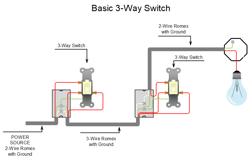
Diagram 1: Power Source to Switch 1, Light to Switch 2
This is one of the most common setups. In this configuration, the power source (hot wire) enters the first switch box, and the light fixture is connected at the second switch box.
Switch 1 (Power Source Side):
- Connect the black (hot) wire from the power source to the common terminal (COM) on Switch 1.
- Connect the two traveler wires to the traveler terminals on Switch 1.
- Use a white wire (neutral) to connect from the neutral wire in the electrical box to the neutral wire of the power source.
- Connect the ground wire to the ground screw on the switch.
Switch 2 (Light Fixture Side):
- Connect the black wire (load) from the light fixture to the common terminal (COM) on Switch 2.
- Connect the two traveler wires from Switch 1 to the corresponding traveler terminals on Switch 2.
- Connect the white wire (neutral) from the light fixture to the neutral wire.
- Connect the ground wire to the ground screw on the switch.
Diagram 2: Power Source to Light Fixture, Switches in Between
In this configuration, the power source goes directly to the light fixture, and the switches are wired between the power source and the light.
Light Fixture Box:
- Connect the black wire (hot) from the power source to the black wire (hot) of the light fixture.
- Connect the white wire (neutral) from the power source to the white wire (neutral) of the light fixture.
- Connect the ground wires.
Switch 1:
- Connect the black wire (hot) to the common terminal (COM) on Switch 1.
- Connect the two traveler wires to the traveler terminals on Switch 1.
- Connect the ground wire to the ground screw on the switch.
Switch 2:
- Connect the two traveler wires from Switch 1 to the corresponding traveler terminals on Switch 2.
- Connect a black wire (load) from the common terminal (COM) to the black wire of the light fixture.
- Connect the ground wire to the ground screw on the switch.
Important Wiring Considerations:
- Wire Colors: Always follow standard wire color conventions: black for hot, white for neutral, and green or bare copper for ground.
- Wire Nuts: Use appropriate-sized wire nuts to securely connect wires. Ensure the connections are tight.
- Grounding: Properly ground all switches and the light fixture for safety.
- Documentation: Take pictures of your existing wiring before you disconnect anything. This can be invaluable for troubleshooting.
- Double-Check: Before restoring power, meticulously double-check all connections to ensure they are correct and secure.
Troubleshooting Common Issues
Even with careful planning, problems can arise. Here are some common issues and their potential solutions:
Light Doesn’t Turn On:
- Check the breaker: Ensure the circuit breaker hasn’t tripped.
- Verify wire connections: Double-check all wire connections, particularly the common terminals.
- Test the light bulb: Make sure the light bulb isn’t burned out.
- Switch orientation: Confirm that the switches are correctly oriented, and the travelers are connected to the correct terminals.
Light Stays On:
- Switch orientation: Ensure the common terminal is wired correctly on both switches.
- Short circuit: Check for any exposed wires that might be touching.
Light Flickers:
- Loose connections: Tighten all wire connections, especially at the switch terminals.
- Faulty bulb or fixture: Test with a new bulb or fixture.
Safety First: When to Call a Professional
While this guide provides detailed instructions, electrical work can be dangerous. If you are not comfortable with any part of the process, or if you encounter complex wiring or unfamiliar situations, it’s crucial to consult a qualified electrician. Never take chances with electrical safety.
Conclusion: Empowering Your Electrical Knowledge
Wiring 3-way switches can seem daunting at first, but with a clear understanding of the diagrams and a methodical approach, it’s a manageable DIY project. By following these step-by-step instructions and prioritizing safety, you can enhance your home’s functionality and gain valuable electrical knowledge. Remember to always turn off the power, double-check your work, and when in doubt, seek professional help. Happy wiring!
FAQs
- Can I use the same wire for the travelers? Yes, the traveler wires should be the same gauge and color, but they can be different colors.
- What size wire should I use for 3-way switches? The wire gauge depends on the circuit’s amperage. Generally, 14 AWG wire is used for 15-amp circuits, and 12 AWG wire is used for 20-amp circuits. Consult your local electrical code for specific requirements.
- Why are there sometimes more than three wires in the switch box? Additional wires may be present if the box also contains a light fixture, outlet, or if the circuit is part of a larger electrical system.
- Can I mix and match different brands of 3-way switches? Yes, you can generally use 3-way switches from different brands, as long as they are designed for the same voltage (usually 120V in North America).
- What is the purpose of the ground wire? The ground wire provides a safe path for electricity to travel back to the electrical panel if a fault occurs, protecting you from electric shock.
