Low battery
Battery level is below 20%. Connect charger soon.


3-Way Switch Wiring Diagrams Finally Explained In A Way Anyone Can Understand
Tired of flickering lights and head-scratching diagrams? The mystery of 3-way switch wiring, often a source of frustration for DIYers and even some seasoned homeowners, is about to be demystified. This article provides a clear, comprehensive, and easy-to-follow guide to understanding and implementing 3-way switch wiring, eliminating the confusion and empowering you to take control of your home’s electrical system. We’ll break down the components, the wiring configurations, and the common pitfalls, all in plain language.
What is a 3-Way Switch and Why Do You Need One?
Before diving into the wiring, let’s clarify the basics. A 3-way switch isn’t actually a “3-way” switch in the sense of three positions. Instead, it allows you to control a single light fixture (or other electrical device) from two different locations. Think of it as a seesaw: when one switch is “up,” the other switch determines whether the light is on or off. Common applications include:
- Hallways: Control the hallway light from both ends.
- Stairwells: Switch the stairwell light from the top and bottom of the stairs.
- Large Rooms: Operate a light from multiple entry points in a large living room or bedroom.
- Outdoor Lighting: Control porch lights or landscape lighting from inside and outside.
Understanding the Key Components: A Quick Breakdown
Before you start wiring, it’s crucial to understand the parts involved. Here’s a breakdown of the key components:
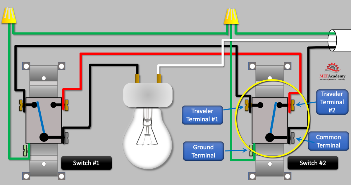
- 3-Way Switches: These switches have three terminals (connection points) and a grounding screw. Two of the terminals are called “travelers” and are typically brass-colored screws. The third terminal, often a different color (like black or dark bronze) or labeled “common,” connects to the power source or the light fixture.
- Light Fixture: The light fixture itself, which requires a power source (hot wire), a neutral wire, and often a ground wire.
- Electrical Cables (Wires): You’ll need specific types of wire, typically:
- 14/3 or 12/3 Wire: This cable contains a black (hot), red (traveler), white (neutral), and bare copper (ground) wire. The “14” or “12” refers to the wire gauge (thickness), with 12-gauge being used for higher amperage circuits.
- 14/2 or 12/2 Wire: This cable contains a black (hot), white (neutral), and bare copper (ground) wire.
- Wire Connectors (Wire Nuts): Used to safely connect wires together.
- Electrical Box(es): To house the switches and make the connections safe.
- Multimeter (Optional, but Recommended): For verifying voltage and ensuring the circuit is de-energized before working.
Decoding the Wiring Diagrams: Two Common Configurations
There are two primary ways to wire 3-way switches:
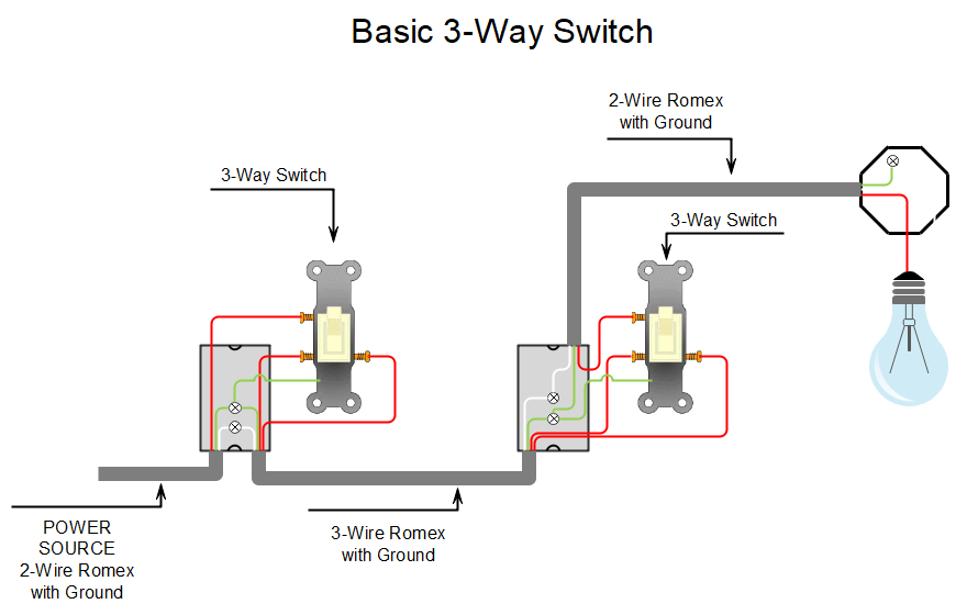
1. The Power to Light Configuration (Power Source at the Light Fixture):
- Power Source: This configuration has the power source (hot and neutral wires) located at the light fixture.
- Wiring: The hot wire from the power source goes to the common terminal of one 3-way switch. The neutral wire from the power source goes to the light fixture. The light fixture then connects to the common terminal of the second 3-way switch. The two traveler wires connect the two 3-way switches together. A neutral wire is also run from the light fixture to the neutral wires in the electrical box.
- Diagram: This setup is often simpler to visualize when starting out.
- Steps:
- Turn OFF the power at the circuit breaker.
- Connect the power source wires at the light fixture.
- Run a 14/3 (or 12/3) cable from the light fixture to each 3-way switch location.
- Connect the hot wire from the power source to the common terminal of one switch.
- Connect the light fixture wire to the common terminal of the other switch.
- Connect the traveler wires between the two switches.
- Connect the ground wires.
- Connect the neutral wires.
- Carefully tuck the wires into the electrical boxes and mount the switches.
- Turn the power back ON and test.
2. The Power to Switch Configuration (Power Source at One of the Switches):
- Power Source: The power source (hot and neutral wires) is located at one of the 3-way switch locations.
- Wiring: The hot wire from the power source goes to the common terminal of the first 3-way switch. The two traveler wires connect the two 3-way switches together. The common terminal of the second switch connects to the light fixture (via a black wire in a 14/2 or 12/2 cable). The neutral wire from the power source is connected to the neutral wire at the light fixture.
- Diagram: This configuration can be slightly more complex to visualize initially.
- Steps:
- Turn OFF the power at the circuit breaker.
- Run a 14/2 (or 12/2) cable from the power source to one of the 3-way switch locations.
- Run a 14/3 (or 12/3) cable from one 3-way switch location to the other 3-way switch location.
- Run a 14/2 (or 12/2) cable from one of the 3-way switch locations to the light fixture.
- Connect the hot wire from the power source to the common terminal of the first 3-way switch.
- Connect the traveler wires between the two switches.
- Connect the common terminal of the second switch to the hot wire of the light fixture.
- Connect the ground wires.
- Connect the neutral wires.
- Carefully tuck the wires into the electrical boxes and mount the switches.
- Turn the power back ON and test.
Important Safety Tips and Considerations
- Always Turn OFF the Power: This is the most critical safety precaution. Double-check with a non-contact voltage tester (NCVT) or multimeter to ensure the wires are de-energized.
- Follow Local Electrical Codes: Wiring regulations can vary by location. Consult your local codes before starting any electrical work.
- Use the Correct Wire Gauge: Ensure you are using the correct gauge wire (14 or 12) based on the circuit’s amperage.
- Tighten Connections Securely: Loose connections can cause arcing and fire hazards.
- Label Your Wires: If you are unsure, label your wires at each end to avoid confusion.
- Grounding is Essential: Properly ground all components for safety.
- If You’re Uncomfortable, Call a Professional: If you are unsure about any part of the process, it’s best to hire a qualified electrician.
Troubleshooting Common Issues
- Light Doesn’t Work at All: Double-check the circuit breaker. Ensure all connections are secure and that the light bulb is working.
- Light Works from One Switch, Not the Other: This usually indicates a problem with the traveler wires or the common wire connection.
- Light Flickers: Loose connections are a common cause of flickering. Tighten all connections.
Conclusion: Mastering 3-Way Switch Wiring
By understanding the components, the wiring configurations, and the safety precautions, you can confidently tackle 3-way switch wiring projects. Remember to take your time, double-check your work, and prioritize safety. With a little patience and this guide, you’ll be well on your way to controlling your lights with ease.
FAQs
Q1: Can I use regular single-pole switches instead of 3-way switches?
A: No, you must use 3-way switches for this configuration. Regular single-pole switches only have two terminals and cannot function correctly in a 3-way setup.
Q2: What happens if I connect the traveler wires to the wrong terminals?
A: The light may not work at all, or the switches may function in reverse, meaning they’ll be opposite to what you expect.
Q3: What’s the difference between 14/3 and 14/2 wire?
A: 14/3 wire contains three insulated wires (black, red, white) and a bare copper ground wire. 14/2 wire contains two insulated wires (black, white) and a bare copper ground wire. The “3” indicates the number of insulated conductors.
Q4: Can I use a multimeter to test the wiring?
A: Yes, a multimeter is a valuable tool for testing voltage and continuity, helping you confirm proper wiring and diagnose problems. However, always ensure the power is OFF before using a multimeter on live wires.
Q5: What if I have more than two locations to control the light?
A: You’ll need to incorporate a 4-way switch in addition to the two 3-way switches. A 4-way switch is wired between the two 3-way switches and allows for control from a third (or more) location. This is a more advanced topic, but the principles remain similar.
