Low battery
Battery level is below 20%. Connect charger soon.


How to Read Piping Diagrams: The Beginner-Friendly Trick Engineers Swear By
Piping diagrams, also known as P&IDs (Piping and Instrumentation Diagrams), can seem like a complex maze of lines, symbols, and labels. For those new to engineering, especially in fields like chemical, mechanical, and process engineering, deciphering these drawings can be daunting. However, understanding P&IDs is crucial for everything from plant operation and maintenance to troubleshooting and design. This article breaks down the process of reading piping diagrams, offering a beginner-friendly trick that seasoned engineers often rely on.
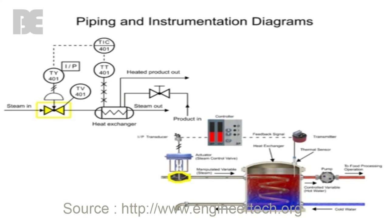
Decoding the Basics: What is a Piping Diagram?
At its core, a piping diagram is a schematic representation of a plant’s piping system. It acts as a blueprint, detailing the entire process flow and showing how different components are interconnected. Think of it as a highly detailed map of how fluids, gases, and other substances move through a system.
Purpose:
- Visualize the process flow.
- Identify all equipment and instrumentation.
- Provide information for installation, operation, and maintenance.
- Support troubleshooting and problem-solving.
- Aid in safety analysis.
Key Components Represented:
- Pipes and their connections.
- Valves (gate, globe, check, etc.).
- Pumps, compressors, and other equipment.
- Instrumentation (pressure sensors, temperature sensors, flow meters, etc.).
- Control systems.
- Process lines and their direction of flow.
- Equipment tags (unique identifiers for each component).
The Beginner-Friendly Trick: Follow the Flow!
The single most effective trick for beginners is to follow the flow of the process. This simple approach allows you to build a mental model of the system and understand how components interact.
Here’s how to apply this method:
- Start at a Defined Point: Choose a starting point, often the inlet of a pump, vessel, or major piece of equipment.
- Identify the Process Line: Locate the process line connected to your starting point. These are typically represented by solid lines, often with a specific line size noted.
- Follow the Line: Trace the line, noting all the components it passes through, such as valves, instruments, and other equipment.
- Observe Direction of Flow: Pay attention to the flow arrows (typically triangle-shaped) that indicate the direction of the fluid/gas.
- Note Equipment Tags: As you follow the line, record the equipment tags (e.g., P-101, FV-205, TE-300). These tags are crucial for referencing the specific components and their functions.
- Repeat: Continue following the flow through the entire system, line by line. As you move through the diagram, you’ll begin to see patterns and relationships.
Understanding Common Symbols and Components
While following the flow is key, understanding the symbols used in P&IDs is essential. Here are some common examples:
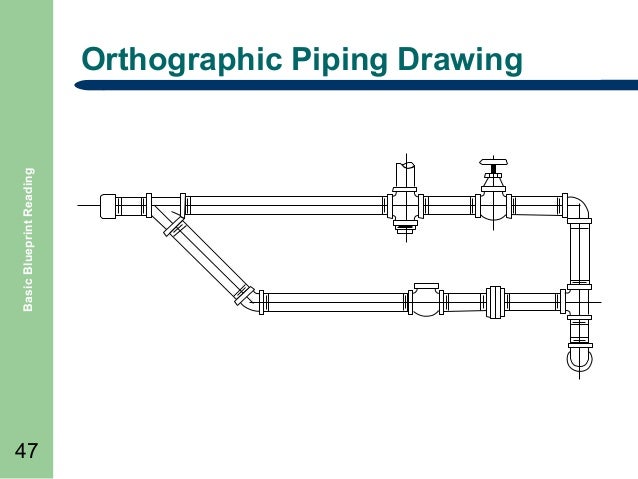
- Pipes: Represented by solid lines, with different line types indicating different process lines (e.g., process, utility, instrument).
- Valves: Various symbols represent different valve types (gate, globe, ball, check, etc.).
- Pumps: Often represented by a circle with a rotating impeller symbol inside.
- Tanks/Vessels: Represented by various shapes (rectangles, cylinders, spheres).
- Instrumentation: Usually represented by circles or squares, with tags identifying the instrument’s function and location. (e.g., PI - Pressure Indicator, TI - Temperature Indicator, FT - Flow Transmitter).
- Equipment: Represented by labeled boxes or other shapes, often with equipment tags.
Learning the symbols takes time and practice. Refer to a standard symbol key or legend, typically found on the P&ID itself, to understand the meaning of each symbol.
Tips for Success: Practice Makes Perfect
- Start Simple: Begin with simpler P&IDs before tackling complex ones.
- Use a Highlighter: Trace the lines with a highlighter to make the flow easier to follow.
- Ask Questions: Don’t hesitate to ask experienced engineers for clarification.
- Refer to Datasheets: When you encounter an unfamiliar component, refer to its datasheet for more detailed information.
- Practice Regularly: The more you practice, the more comfortable you will become with reading P&IDs.
- Use Software: CAD software like AutoCAD, or dedicated P&ID software can make the process easier and more interactive.
Conclusion: Mastering the Language of Process Engineering
Reading piping diagrams is a fundamental skill for anyone working in process engineering. By utilizing the “follow the flow” technique, familiarizing yourself with common symbols, and practicing consistently, you can unlock the secrets hidden within these complex drawings. This beginner-friendly approach, combined with ongoing learning and referencing, will empower you to confidently navigate the world of P&IDs and contribute effectively to your projects.
Frequently Asked Questions (FAQs)
1. What is the difference between a P&ID and a PFD (Process Flow Diagram)?
A PFD (Process Flow Diagram) is a simplified version of a P&ID. It focuses on the major process flow and equipment, without the detailed instrumentation and control information found in a P&ID. PFDs are used for conceptual design, while P&IDs are used for detailed design, construction, and operation.
2. Where can I find standard symbols for P&IDs?
Industry standards like ISA (International Society of Automation) and relevant engineering standards provide comprehensive lists of P&ID symbols. These standards are essential references for understanding the language of P&IDs. They are often included in the P&ID itself.
3. How important are equipment tags?
Equipment tags are extremely important. They are unique identifiers that allow you to quickly find and reference specific components within the system. They are used in documentation, maintenance records, and troubleshooting procedures.
4. What software is commonly used for creating and viewing P&IDs?
Common software used for creating P&IDs includes AutoCAD P&ID, SmartPlant P&ID, and similar specialized software. These tools offer features for creating, editing, and managing P&ID drawings. Viewing can be done with any software that can open the file type, such as PDF viewers or CAD viewers.
5. How can I improve my understanding of P&IDs beyond just reading them?
Beyond reading, understanding the underlying process is crucial. Learn about the process being depicted (e.g., chemical reaction, fluid transport). Additionally, learning about the purpose and function of each component will significantly enhance your comprehension. Consider training courses or online resources that cover process engineering principles.
