Low battery
Battery level is below 20%. Connect charger soon.


Icom Microphone Pinout – Complete Wiring & Setup Guide
Are you a ham radio enthusiast, a shortwave listener, or someone who just appreciates crystal-clear communication? If you own an Icom transceiver, understanding the microphone pinout is crucial for optimal performance and achieving the audio quality you desire. This comprehensive guide will walk you through the Icom microphone pinout, providing detailed wiring diagrams, setup instructions, and troubleshooting tips to ensure your transmissions are heard loud and clear.
Understanding the Importance of Microphone Pinout
The microphone pinout defines the connections between your microphone and your Icom transceiver. Incorrect wiring can lead to:
- No audio transmission: You won’t be heard.
- Garbled or distorted audio: Your signal will be unintelligible.
- Damage to your radio or microphone: Incorrect voltage or grounding can cause serious issues.
- Poor audio quality: Even if you can transmit, a poorly wired microphone can sound weak or noisy.
This guide empowers you to avoid these pitfalls by providing the necessary knowledge to correctly wire and configure your microphone for your Icom radio.
Identifying Your Icom Microphone Connector
Before diving into the pinout, it’s vital to identify the type of microphone connector your Icom transceiver uses. This will dictate the specific wiring scheme you need. Common Icom microphone connectors include:
- 8-Pin Round Connector (Often referred to as “Icom 8-pin”): This is perhaps the most common connector found on many Icom HF and VHF transceivers.
- RJ45 (Ethernet-style connector): Found on some newer Icom models.
- Modular 8-pin (Similar to an RJ45, but with a different pin arrangement): Some older and specific models use this variant.
- Other proprietary connectors: Some older or specialized Icom radios might use unique connectors. Always consult your radio’s manual to identify the exact connector type.
Crucial Step: Always refer to your specific Icom radio’s manual for the definitive pinout diagram. While this guide provides general information, individual models can sometimes have variations.
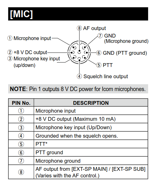
Icom 8-Pin Round Microphone Pinout
The 8-pin round connector is prevalent across many Icom transceivers. Here’s a typical pinout:
- Pin 1: Microphone Input (MIC +) - The positive audio signal from the microphone element.
- Pin 2: PTT (Push-to-Talk) Input - Activates the transmitter when grounded.
- Pin 3: Ground (GND) - Common ground for the microphone and PTT switch.
- Pin 4: Microphone Ground (MIC GND) - Ground for the microphone element.
- Pin 5: Up/Down (Channel Selection) - Often used for channel up/down control.
- Pin 6: CW Key Input (CW) - For connecting a Morse code key.
- Pin 7: Power (DC +) - Provides power for electret microphones (typically +8V DC).
- Pin 8: Shield - Often connected to the microphone’s shield and chassis ground.
Wiring Considerations for 8-Pin Round Connectors:
- Microphone Element: The microphone element (dynamic or electret) connects to Pins 1 (MIC +) and 4 (MIC GND).
- PTT Switch: The PTT switch connects between Pin 2 (PTT) and Pin 3 (GND). Pressing the switch grounds Pin 2, activating the transmitter.
- Electret Microphones: Electret microphones typically require a DC voltage (usually +8V) provided on Pin 7. You may need to add a resistor (typically 2.2k ohms to 10k ohms) in series with the positive lead of the electret microphone to limit current.
- Dynamic Microphones: Dynamic microphones do not need Pin 7 connected, as they generate their own signal.
- Shielding: Connect the microphone cable’s shield to Pin 8 (Shield) to reduce noise.
RJ45 Microphone Pinout for Icom Radios
While the specific pinout can vary slightly depending on the model, here’s a general RJ45 pinout for Icom microphones:
- Pin 1: Microphone Input (MIC +)
- Pin 2: PTT (Push-to-Talk)
- Pin 3: Ground (GND)
- Pin 4: Up/Down
- Pin 5: Microphone Ground (MIC GND)
- Pin 6: +8V (for Electret Microphone)
- Pin 7: CW Key Input
- Pin 8: Shield
Wiring Considerations for RJ45 Connectors:
- The principles are similar to the 8-pin round connector, but the pin assignments are different.
- Consult your radio’s manual for the exact pin assignments.
- Ensure you use a crimp tool specifically designed for RJ45 connectors to ensure proper connections.
Setting Up Your Microphone: Testing and Adjustments
After wiring your microphone, follow these steps to ensure proper functionality:
- Power On: Turn on your Icom transceiver.
- Connect Your Microphone: Plug your wired microphone into the appropriate connector on your radio.
- Transmit Test: Press the PTT button on your microphone or the rig’s PTT (if applicable). The radio should switch to transmit mode.
- Receive Test: Ask another ham operator or use a separate receiver to listen to your transmission.
- Audio Adjustments: Adjust the microphone gain on your radio to achieve optimal audio levels. Avoid over-modulation (audio distortion). Listen carefully to your audio reports and make adjustments as needed.
- Squelch: Adjust the squelch setting on your radio to eliminate background noise.
Troubleshooting Common Microphone Problems
- No Audio:
- Check the microphone wiring for loose connections or incorrect pin assignments.
- Verify the microphone element is functioning.
- Ensure the microphone gain is not set too low.
- Distorted Audio:
- Reduce the microphone gain on your radio.
- Check for short circuits in the microphone wiring.
- Verify that the microphone element is compatible with your radio.
- Background Noise:
- Ensure proper grounding.
- Check the microphone cable for damage.
- Try using a shielded microphone cable.
- Adjust the squelch setting on your radio.
- PTT Not Working:
- Verify the PTT switch wiring.
- Check for a short circuit or open circuit in the PTT circuit.
- Ensure the radio is in the correct mode (e.g., FM, SSB).
Conclusion: Achieving Clear Communications
Understanding and correctly wiring your Icom microphone pinout is essential for enjoying clear, reliable communications. By carefully following the pinout diagrams, wiring instructions, and setup procedures outlined in this guide, you can ensure your transmissions are heard loud and clear. Remember to always consult your radio’s manual for the most accurate and up-to-date information. Happy transmitting!
Frequently Asked Questions (FAQs)
Q1: Can I use any microphone with my Icom radio?
A: Not necessarily. You need a microphone that is compatible with your Icom radio’s pinout and impedance requirements. Dynamic microphones and electret microphones are common choices. Ensure the microphone’s wiring matches the pinout of your radio’s connector.
Q2: What is the purpose of Pin 7 (Power) on the 8-pin connector?
A: Pin 7 provides +8V DC power to electret condenser microphones. This voltage is necessary for the electret element to function. If you are using a dynamic microphone, this pin is typically not connected.
Q3: How do I know if my microphone is dynamic or electret?
A: Check the microphone’s specifications or manufacturer’s documentation. Electret microphones usually have three wires (positive, negative, and ground), while dynamic microphones typically have two. If you aren’t sure, consult the microphone’s datasheet.
Q4: What if my Icom radio uses a different connector than the 8-pin or RJ45?
A: Always consult your radio’s manual. The manual will provide the specific pinout diagram for your radio’s connector. You may need to purchase an adapter or custom-wire a microphone to match the connector.
Q5: Can I damage my radio by incorrectly wiring the microphone?
A: Yes. Incorrect wiring, especially incorrect voltage or grounding, can potentially damage your radio’s audio input circuitry. Always double-check your wiring and consult the radio’s manual before making any connections.
