Low battery
Battery level is below 20%. Connect charger soon.


Indak Ignition Switch Wiring Diagram: The Fix Small Engines Can’t Run Without
Your lawnmower sputters, your generator coughs, and your mini-bike sits idle. The culprit? A faulty ignition switch. Often overlooked, the ignition switch is the gatekeeper of power for your small engine, and its wiring diagram is the key to unlocking its secrets. This article delves into the critical role of the Indak ignition switch, providing a comprehensive guide to understanding its wiring, troubleshooting common issues, and getting your small engine roaring back to life.
The Crucial Role of the Indak Ignition Switch
The Indak ignition switch, a common component in various small engines, controls the flow of electricity that starts and operates your equipment. Think of it as the brain’s command center, dictating when power is supplied to the spark plug, the starter motor, and other essential components. Without a functioning ignition switch and its correctly wired connections, your engine is effectively dead in the water.
Understanding the Indak Ignition Switch Wiring Diagram: A Visual Guide
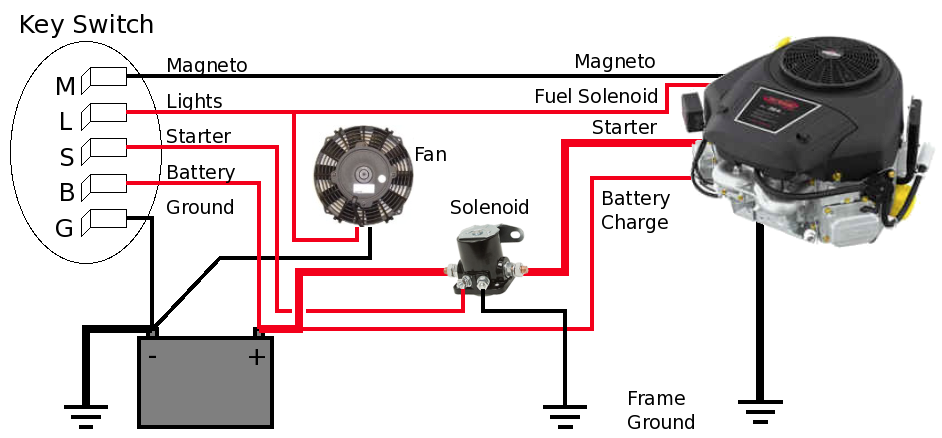
The wiring diagram is the roadmap to understanding how your Indak ignition switch is connected to the rest of your engine’s electrical system. It’s usually a simplified representation showing the switch’s terminals and the wires that connect to them. While specific diagrams vary depending on the engine and the switch’s features, some common elements remain constant. Let’s break down the key components you’ll typically encounter:
- Terminals: These are the connection points on the switch, often labeled with letters or numbers. Common labels include:
- B (Battery): Receives power directly from the battery.
- I (Ignition): Supplies power to the ignition coil, which generates the spark.
- S (Starter): Activates the starter motor to crank the engine.
- L (Lights): Powers the lights, if equipped.
- G (Ground): Often used for grounding the switch itself or other components.
- Wires: Wires are color-coded to help you identify the function of each connection. Common wire colors include:
- Red: Typically indicates power from the battery.
- Black: Often signifies ground.
- Yellow: May be used for lights or accessories.
- Blue/Green: Commonly associated with the ignition system.
- Positions: The switch has different positions (Off, On, Start) which correspond to different circuit connections.
Common Wiring Issues and Troubleshooting Tips
A malfunctioning ignition switch or incorrect wiring can lead to a range of problems, from a complete no-start situation to intermittent operation. Here are some common issues and troubleshooting steps:
- Engine Won’t Start at All:
- Check the Battery: Ensure the battery is fully charged and making good contact.
- Inspect the Wiring: Look for loose connections, corrosion, or damaged wires at the switch terminals.
- Test the Switch: Use a multimeter to check for continuity between the terminals in the “On” and “Start” positions. If there’s no continuity, the switch might be faulty.
- Examine the Fuse: Verify the fuse protecting the ignition circuit is intact.
- Engine Starts but Dies Immediately:
- Ignition Coil Connection: Ensure the wire connecting to the ignition coil is secure and properly connected.
- Grounding Issues: Check the ground wire connections for corrosion or looseness.
- Engine Runs Intermittently:
- Loose Connections: Vibrate the wires near the switch to see if it causes the engine to stall or start. This can pinpoint a loose connection.
- Corrosion: Clean the switch terminals with contact cleaner and a small brush.
How to Obtain and Interpret an Indak Ignition Switch Wiring Diagram
Finding the correct wiring diagram for your specific engine and Indak ignition switch is crucial. Here’s how:
- Consult the Engine’s Manual: The owner’s manual or service manual for your engine (e.g., Briggs & Stratton, Honda, Kohler) is the primary source. Look for the electrical diagrams section.
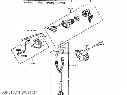
- Identify the Switch Model: Check the switch itself for a model number or part number. This will help you narrow down your search.
- Online Resources: Search online using the engine make and model, along with “Indak ignition switch wiring diagram.” You can often find diagrams on manufacturer websites, parts suppliers, and online forums dedicated to small engine repair.
- Professional Assistance: If you are unsure or uncomfortable working with electrical systems, consult a qualified small engine repair technician.
Safety Precautions
Working with electrical systems requires caution. Always disconnect the negative terminal of the battery before working on the ignition switch wiring to prevent accidental shorts and electrical shocks. Use insulated tools and avoid touching exposed wires while the battery is connected.
Conclusion: Keeping Your Engine Running Smoothly
The Indak ignition switch is a vital component of your small engine, and understanding its wiring diagram is essential for troubleshooting and repair. By following the guidelines outlined in this article, you can effectively diagnose and resolve common issues, ensuring your equipment operates reliably. Remember to always prioritize safety and, when in doubt, seek professional assistance.
Frequently Asked Questions (FAQs)
1. Where can I find the wiring diagram for my specific Indak ignition switch?
The best places to find a wiring diagram are the engine’s owner’s manual, service manuals, or online resources using the engine’s make and model, and the ignition switch’s model number.
2. What should I do if I suspect a faulty Indak ignition switch?
First, check all wiring connections for looseness or corrosion. Then, use a multimeter to test for continuity between the switch terminals in the “On” and “Start” positions. If there’s no continuity, the switch may need to be replaced.
3. Can I use a generic wiring diagram for my Indak ignition switch?
While generic diagrams can be helpful for understanding basic principles, it’s always best to use a diagram specific to your engine and switch model. This ensures accurate connections and avoids potential damage.
4. What tools do I need to work on the ignition switch wiring?
You’ll need basic tools like screwdrivers, wire strippers/crimpers, a multimeter, and electrical tape or heat shrink tubing. It’s also helpful to have contact cleaner and a small brush for cleaning terminals.
5. Is it safe to replace the Indak ignition switch myself?
Replacing the ignition switch is a manageable task for those with basic mechanical skills. Just be sure to disconnect the battery, carefully label or photograph the existing wiring before disconnecting it, and follow the wiring diagram precisely. If you’re uncomfortable, seek professional help.
