Low battery
Battery level is below 20%. Connect charger soon.


John Deere 4040 Ignition Wiring Diagram: The Complete Guide for Smooth Repairs
The John Deere 4040 tractor, a workhorse of its era, remains a valuable asset for many farmers and enthusiasts. However, like any piece of machinery, it requires maintenance and occasional repairs. One of the most common issues encountered is with the ignition system. A faulty ignition can prevent your 4040 from starting, leaving you stranded in the field. This is where a clear understanding of the ignition wiring diagram becomes crucial. This comprehensive guide provides you with the information you need to diagnose and repair ignition problems on your John Deere 4040, ensuring smooth operation and minimizing downtime.
Understanding the Importance of the Ignition Wiring Diagram
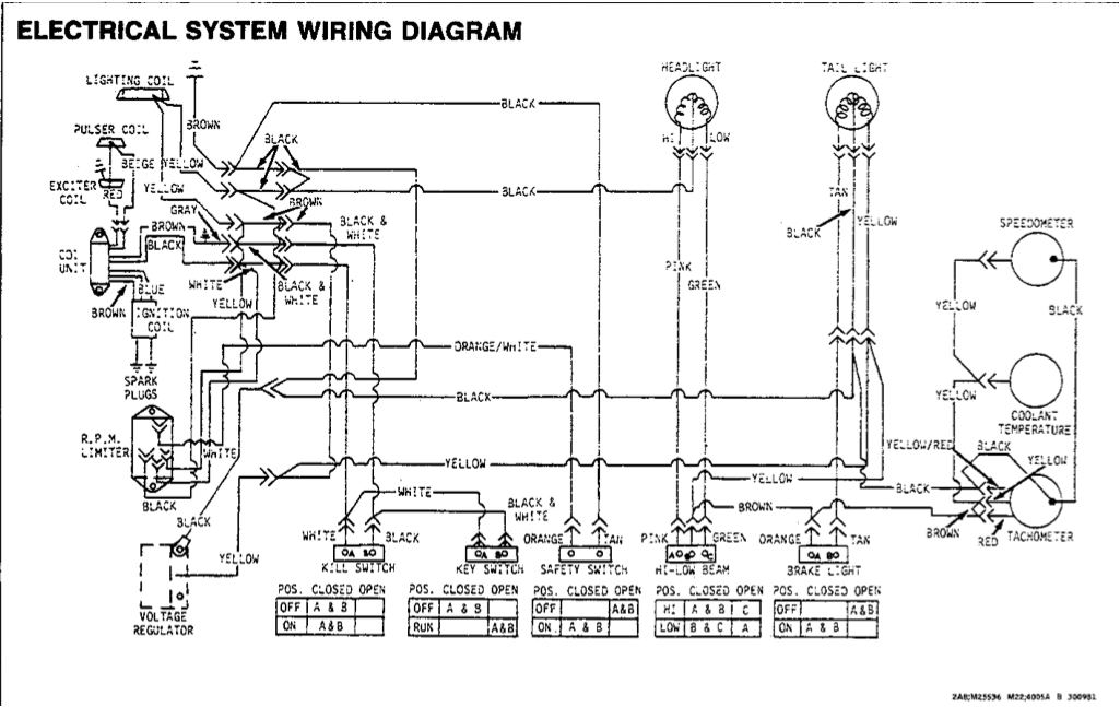
A well-defined ignition wiring diagram is the blueprint for your tractor’s starting system. It illustrates the connections between all components, including:
- The Ignition Switch: The central control point for starting and running the engine.
- The Starter Solenoid: A relay that engages the starter motor.
- The Starter Motor: The electric motor that cranks the engine.
- The Battery: Provides the power source for the entire system.
- Fuses and Relays: Protects the electrical circuits from damage.
- Wiring Harness: The network of wires that connects all components.
By consulting the wiring diagram, you can:
- Identify the correct wires: Ensuring proper connections and preventing short circuits.
- Trace the flow of electricity: Understanding the path the current takes from the battery to the starter motor.
- Locate potential faults: Pinpointing the location of a problem based on the diagram.
- Safely troubleshoot and repair: Minimizing the risk of electrical shock or damage to the tractor.
Locating Your John Deere 4040 Ignition Wiring Diagram
Finding the correct wiring diagram for your John Deere 4040 is the first step. Here are the most common ways to access this valuable resource:
- John Deere Technical Manuals: The official John Deere service manuals are the most reliable and detailed source. They often include comprehensive wiring diagrams specific to your tractor’s model and serial number. These manuals are available for purchase online or at authorized John Deere dealerships.
- Online Resources: Numerous websites and forums dedicated to tractor repair offer wiring diagrams for the John Deere 4040. Search terms like “John Deere 4040 wiring diagram,” “John Deere 4040 ignition wiring,” or “John Deere 4040 electrical diagram” will likely yield useful results.
- Parts Catalogs: Some parts catalogs may include basic wiring diagrams, particularly those that focus on electrical components.
- Professional Mechanics: If you’re unsure about interpreting the diagram or performing the repairs, consulting a qualified John Deere mechanic is recommended.
Deciphering the John Deere 4040 Ignition Wiring Diagram
Once you have the wiring diagram, understanding its symbols and conventions is essential. Here are some key elements:
- Wire Colors: Wires are typically color-coded to identify their function and circuit. Common colors include:
- Red: Often used for positive (+) power connections.
- Black: Commonly used for ground (-) connections.
- Yellow: Used for lights or other accessories.
- Blue: Used for specific circuits, such as the ignition circuit.
- Symbols: Standard electrical symbols are used to represent components like:
- Battery: Represented by two parallel lines, one longer than the other.
- Ignition Switch: A switch with multiple positions (Off, Run, Start).
- Starter Solenoid: A rectangle with a coil symbol inside.
- Starter Motor: A circle with a “M” inside.
- Fuses: Small rectangles or squares with a fuse symbol inside.
- Ground: Represented by a symbol resembling a three-pronged fork.
- Circuit Tracing: The diagram shows how the wires connect to each component, allowing you to trace the flow of electricity.
Step-by-Step Troubleshooting for Ignition Problems
Armed with the wiring diagram, you can systematically troubleshoot ignition problems:
- Safety First: Disconnect the negative (-) battery cable before working on any electrical components.
- Visual Inspection: Examine the wiring harness for any signs of damage, such as frayed wires, corrosion, or loose connections.
- Check Fuses: Locate the fuse box and inspect all fuses. Replace any blown fuses with the correct amperage.
- Test the Battery: Ensure the battery is fully charged and capable of providing sufficient power. Use a multimeter to check the voltage.
- Test the Ignition Switch: Use a multimeter to test the ignition switch for continuity in each position (Off, Run, Start).
- Check the Starter Solenoid: With the ignition switch in the “Start” position, listen for a clicking sound from the solenoid. If no click is heard, test the solenoid with a multimeter.
- Test the Starter Motor: If the solenoid is working, but the engine won’t crank, the starter motor may be faulty. Test the motor directly by applying power to it.
- Ground Connections: Check all ground connections for corrosion or looseness. Ensure a good ground connection is essential for proper electrical function.
- Wiring Continuity: Use a multimeter to check for continuity in the wiring harness.
Common Ignition Problems and Solutions
- No Crank/No Start:
- Possible Causes: Dead battery, faulty ignition switch, bad starter solenoid, bad starter motor, blown fuse, damaged wiring.
- Solutions: Charge or replace the battery, replace the ignition switch, replace the solenoid, replace the starter motor, replace the fuse, repair wiring.
- Engine Cranks but Won’t Start:
- Possible Causes: Faulty ignition coil, fuel delivery problems, spark plug issues.
- Solutions: Test the ignition coil, check fuel pump and lines, inspect and replace spark plugs.
- Intermittent Starting:
- Possible Causes: Loose connections, corroded wires, faulty relays.
- Solutions: Tighten connections, clean or replace corroded wires, replace relays.
Conclusion: Ensuring Your John Deere 4040’s Longevity
By utilizing the John Deere 4040 ignition wiring diagram, you gain the knowledge and tools necessary to diagnose and repair ignition problems effectively. This guide provides the information you need to understand the diagram, troubleshoot common issues, and maintain your tractor’s reliable performance. Proper maintenance and timely repairs will ensure that your John Deere 4040 continues to serve you for years to come.
Frequently Asked Questions (FAQs)
- Where can I find the most accurate John Deere 4040 ignition wiring diagram? The most accurate diagrams are found in the official John Deere service manuals.
- What tools do I need to troubleshoot the ignition system? You’ll need a multimeter, basic hand tools (wrenches, screwdrivers), and possibly a wire stripper and crimper.
- What should I do if I’m not comfortable working with electrical systems? It’s best to consult a qualified John Deere mechanic for assistance.
- Can I use a generic wiring diagram for my John Deere 4040? While some generic diagrams may be helpful, they may not be specific to your model. It is always best to use a diagram specific to your tractor.
- How do I know if my starter solenoid is bad? Test the solenoid by listening for a clicking sound when the ignition switch is turned to the “Start” position. If no click is heard, test the solenoid with a multimeter for continuity.
