Low battery
Battery level is below 20%. Connect charger soon.


Latching Relay Wiring Diagram – Step-by-Step Guide
Do you need a reliable way to maintain a circuit’s state even after power is removed? Are you looking for a component that remembers its “on” or “off” position? Then a latching relay is the perfect solution. This versatile device is crucial in numerous applications, from home automation and industrial control systems to automotive circuits. This comprehensive guide will walk you through the process of understanding and wiring a latching relay, ensuring you can confidently implement it in your projects. We’ll delve into the components, wiring diagrams, and safety precautions, empowering you to harness the power of this essential electrical component.
What is a Latching Relay?
Before diving into the wiring, it’s essential to grasp the fundamentals. Unlike standard relays that require continuous power to maintain their state, a latching relay (also known as a bistable relay) utilizes a short pulse of current to switch between two stable states: “on” and “off.” Once switched, it remains in that position without any power consumption until another pulse triggers the opposite state.
This characteristic makes latching relays ideal for:
- Power conservation: They consume power only during switching, making them energy-efficient.
- Memory function: They “remember” their last state, even during power outages.
- Remote control: They can be triggered by momentary switches or pulses from a control system.
Components You’ll Need
Before you begin wiring, gather the necessary components:
- Latching Relay: The specific type will dictate the voltage and current ratings. Choose one appropriate for your circuit’s requirements.
- Power Source: A DC power supply (often 12V, 24V, or custom voltage) is commonly used. Ensure it matches the relay’s coil voltage.
- Momentary Switches (or Control Circuit): Two switches are typically used: one for “Set” (turn on) and one for “Reset” (turn off). Alternatively, you can use a control circuit that generates the necessary pulses.
- Load (Device to be controlled): This could be a light bulb, motor, solenoid, or any device you want to control. Ensure the load’s voltage and current requirements are within the relay’s contact ratings.
- Wiring: Appropriate gauge wires are crucial. Consider the current flowing through the wires to prevent overheating.
- Connectors (Optional): Wire connectors, crimp terminals, or terminal blocks can simplify the wiring and improve reliability.
- Multimeter: For testing continuity and voltage.
- Safety Equipment: Safety glasses and appropriate clothing.
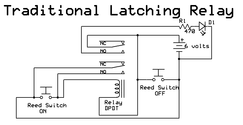
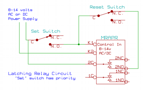
Step-by-Step Wiring Guide with Diagram
Wiring a latching relay can seem daunting at first, but this step-by-step guide, along with a simplified wiring diagram, will simplify the process. Always consult the relay’s datasheet for specific pin assignments and voltage ratings, as they can vary between manufacturers and models.
Simplified Wiring Diagram (Example using a DPDT Latching Relay):
                                 +V (Power Supply)
                                 |
                                 |  (Set Switch)
                                 |-------|
                                 |       |
                                 |       |--- Relay Coil 1 (Set)
                                 |       |
                                 |       |
                                 |-------|
                                 |
                                 +-------- Relay Common (COM)
                                 |        |
                                 |        |--- Load
                                 |        |
                                 |        |--- Ground (for Load)
                                 |        |
                                 |  (Reset Switch)
                                 |-------|
                                 |       |
                                 |       |--- Relay Coil 2 (Reset)
                                 |       |
                                 |       |
                                 |-------|
                                 |
                                 -V (Power Supply Ground)
Steps:
- Identify the Pins: Locate the relay’s datasheet to identify the coil pins (for “Set” and “Reset”) and the common (COM), normally open (NO), and normally closed (NC) contact pins. DPDT (Double Pole Double Throw) relays will have two sets of COM/NO/NC contacts.
- Connect the Power Supply: Connect the positive (+) and negative (-) terminals of your power supply to the appropriate terminals on the relay. Important: Double-check the voltage rating of the relay’s coil and ensure it matches your power supply.
- Wire the Set Switch (On):
- Connect one side of your “Set” momentary switch to the positive (+) terminal of the power supply.
- Connect the other side of the “Set” switch to the “Set” coil terminal on the relay.
- Connect the negative (-) terminal of the power supply (ground) to the other terminal of the “Set” coil.
- Wire the Reset Switch (Off):
- Connect one side of your “Reset” momentary switch to the positive (+) terminal of the power supply.
- Connect the other side of the “Reset” switch to the “Reset” coil terminal on the relay.
- Connect the negative (-) terminal of the power supply (ground) to the other terminal of the “Reset” coil.
- Connect the Load:
- Connect one side of your load (e.g., a light bulb) to the common (COM) terminal of the relay.
- Connect the other side of your load to the positive (+) terminal of your power supply.
- Connect the negative (-) terminal of your power supply (ground) to the ground of your load. Note: If you are using a DPDT relay, you can use the second set of contacts to control a different load, or to control a circuit in reverse.
- Testing: Before applying power to your load, use a multimeter to test for continuity between the COM and NO contacts when the relay is “set” (on). Then, test for continuity between the COM and NC contacts when the relay is “reset” (off).
- Apply Power and Test: Apply power to the circuit. Briefly press the “Set” switch. The load should turn on. Press the “Reset” switch. The load should turn off.
Safety Precautions
- Always disconnect power before making or modifying any wiring connections.
- Double-check all wiring to ensure accuracy before applying power.
- Use the correct wire gauge for the expected current draw to prevent overheating.
- Protect the circuit with a fuse or circuit breaker appropriate for the load.
- Avoid working with high voltages if you are not experienced.
- Consult a qualified electrician if you are unsure about any aspect of the wiring.
Troubleshooting Tips
- Load not turning on:
- Verify the power supply is working and providing the correct voltage.
- Check the fuse or circuit breaker.
- Confirm the relay coil is receiving the pulse signal from the set/reset switches. Use a multimeter to test for voltage across the coil when the switch is pressed.
- Inspect the wiring for loose connections or short circuits.
- Use a multimeter to test for continuity between the COM and NO/NC contacts when the relay should be switched.
- Relay not switching:
- Ensure the relay coil voltage matches the power supply voltage.
- Check for proper polarity of the power supply to the relay coil.
- Inspect the wiring to the set/reset switches.
- The relay might be defective. Try a different relay.
Conclusion
Wiring a latching relay can seem complex at first, but with careful planning and execution, it’s a manageable project. By understanding the components, following the step-by-step guide, and prioritizing safety, you can successfully integrate this valuable component into your projects. Remember to always consult the relay’s datasheet and exercise caution throughout the process. Now you’re well-equipped to harness the efficiency and versatility of latching relays in your electrical endeavors.
Frequently Asked Questions (FAQs)
- 1. What is the difference between a latching relay and a standard relay? A standard relay requires continuous power to maintain its state, whereas a latching relay uses a short pulse to switch and maintains its state without power.
- 2. Can I use a single switch for both set and reset? Yes, with the addition of some external circuitry (e.g., a flip-flop circuit) to generate separate set and reset pulses from a single switch. This is a more advanced implementation.
- 3. What happens if the power fails while the latching relay is in the “on” state? The relay will remain in the “on” state. It will not revert to the “off” state until a reset pulse is applied.
- 4. How do I select the right latching relay for my project? Consider the voltage and current ratings of your load, the voltage of your power supply, and the number of poles and throws (SPDT, DPDT, etc.) you need. Always consult the relay’s datasheet.
- 5. Can I use a microcontroller to control a latching relay? Yes, a microcontroller is an excellent way to control latching relays. The microcontroller can generate the short pulses needed to set and reset the relay. You’ll need to interface the microcontroller’s output pins to the relay’s coil terminals, typically using a transistor to amplify the signal.
