Low battery
Battery level is below 20%. Connect charger soon.


Mic Wiring Diagrams Explained So Simple Anyone Can Follow
Are you a musician, podcaster, or content creator struggling with microphone wiring? Perhaps you’re setting up a home studio, replacing a faulty cable, or just trying to understand how your microphone actually works. The jumble of wires and confusing diagrams can feel overwhelming, but fear not! This guide breaks down mic wiring diagrams into easily digestible steps, making the process simple enough for anyone to understand, regardless of their technical background. We’ll demystify the jargon and provide clear instructions so you can confidently connect your microphone and get back to what you do best: creating!
Understanding the Basics: What You Need to Know First
Before diving into diagrams, let’s establish some fundamental concepts. Understanding these will make the wiring process much smoother.
Microphone Types: Different microphones require different wiring configurations. The most common types are:
- Dynamic Microphones: Robust and generally require no external power.
- Condenser Microphones: Require phantom power (usually +48V) to operate.
- USB Microphones: Contain their own built-in preamps and usually connect directly to a computer via USB. This guide primarily focuses on dynamic and condenser microphones that use XLR connectors.
Connectors: The most common connector used for microphones is the XLR connector (also known as a Cannon connector). It has three pins.
Balanced vs. Unbalanced Signals: Microphone signals are typically balanced to reduce noise interference. This means the signal is carried on two wires, and the third wire acts as a ground.
Phantom Power: Condenser microphones require phantom power, which is supplied through the XLR cable. This power is usually provided by a mixing console, audio interface, or dedicated phantom power supply.
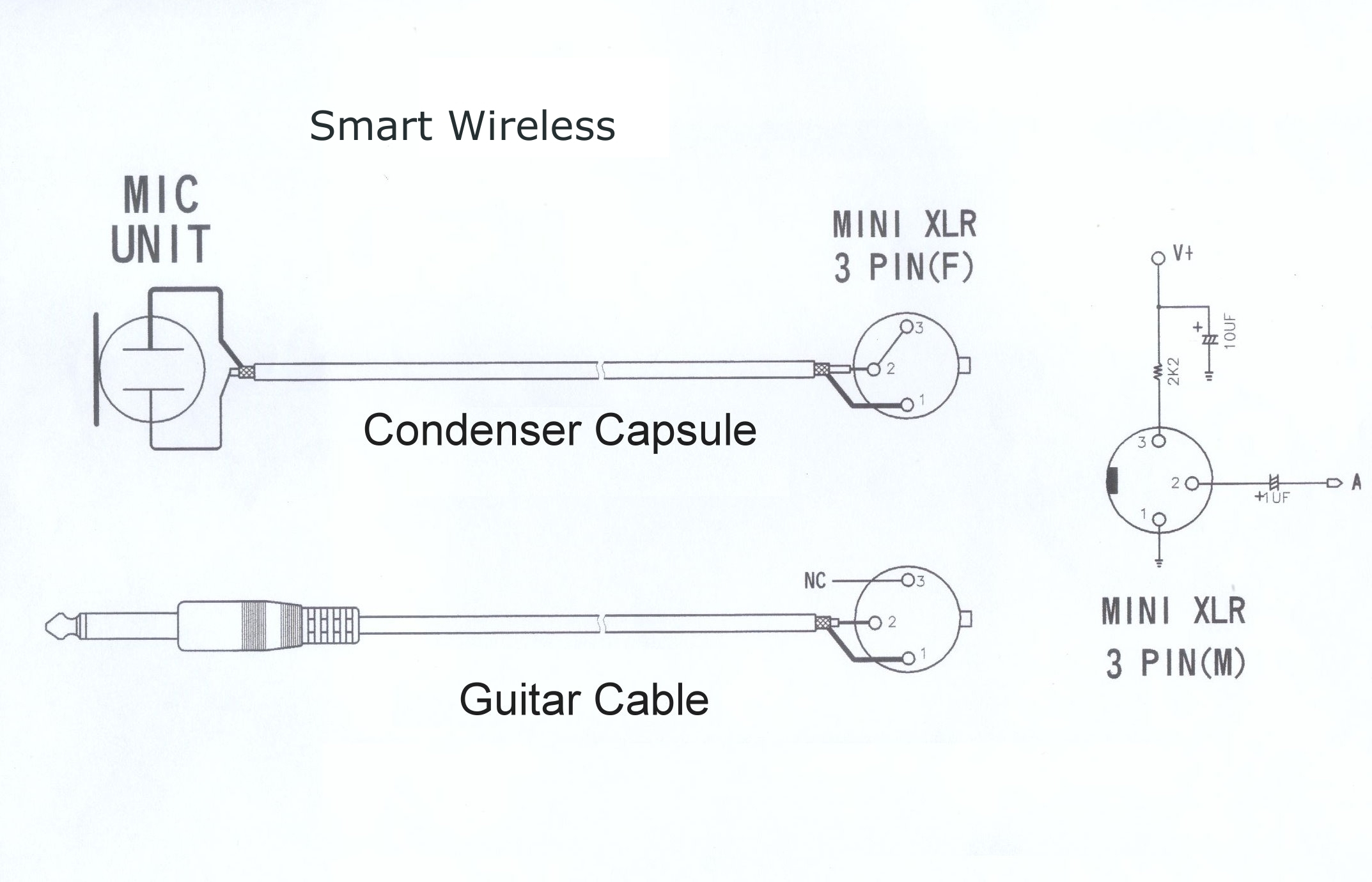
Deciphering the XLR Wiring Diagram: The Three Pins Explained
The key to understanding mic wiring diagrams lies in understanding the three pins of an XLR connector. Here’s a breakdown:
Pin 1: Ground (Shield)
- Provides a shield against electromagnetic interference (EMI) and radio frequency interference (RFI).
- Connected to the metal chassis of the microphone and the audio device to which it’s connected.
Pin 2: Positive (+) / Hot
- Carries the positive signal of the audio.
- Often carries the positive side of phantom power for condenser microphones.
Pin 3: Negative (-) / Cold
- Carries the negative signal of the audio.
- Used with Pin 2 to create a balanced signal.
Step-by-Step Guide to Wiring an XLR Microphone Cable
Let’s walk through the process of wiring an XLR cable. This assumes you have the necessary components:
- XLR Connector (Male or Female, depending on your microphone and audio device)
- Microphone Cable (typically two-conductor shielded cable)
- Soldering Iron & Solder (recommended for a secure connection)
- Wire Strippers
Here’s a simple breakdown:
Prepare the Cable:
- Strip the outer jacket of the microphone cable, exposing the conductors (usually two wires and a shield).
- Strip the insulation from the ends of each conductor.
Connect to the XLR Connector:
- Identify the Pins: Locate the numbered pins on the XLR connector.
- Pin 1 (Ground): Connect the shield wire to Pin 1. If your cable has a separate drain wire, connect it to Pin 1 as well.
- Pin 2 (Hot): Connect one of the conductors to Pin 2.
- Pin 3 (Cold): Connect the other conductor to Pin 3.
- Solder (Optional but Recommended): Use a soldering iron and solder to create a secure connection between the wires and the pins.
Assemble the Connector:
- Carefully reassemble the XLR connector, ensuring all wires are properly secured.
- Make sure the strain relief (usually a clamp) is securely fastened to the cable to prevent it from pulling loose.
Test the Connection:
- Connect the cable to your microphone and audio device.
- Speak into the microphone and check for a clear audio signal.
Troubleshooting Common Wiring Issues
Even with the clearest instructions, things can go wrong. Here’s how to troubleshoot:
No Sound:
- Double-check all connections, especially Pin 2 and Pin 3.
- Ensure the microphone is powered (if it’s a condenser microphone).
- Verify that the audio device’s input is set correctly.
- Check the cable with a multimeter to look for opens or shorts.
Hum or Noise:
- Ensure the shield wire (Pin 1) is properly connected.
- Check for ground loops (try lifting the ground on one of your connected devices).
- Make sure your wiring is well-shielded.
- Examine the cable and connectors for damage.
Weak Signal:
- Check the wiring for correct polarity.
- Ensure the microphone is compatible with the audio device.
- Test the microphone with a known good cable.
H3: Wiring for a Stereo Microphone (If Applicable)
Some microphones offer stereo output. In this case, you’ll often find two XLR connectors, one for the left channel and one for the right. The wiring process is the same as described above, but you’ll be wiring two separate cables. Make sure each cable is connected correctly to the appropriate input on your audio interface or mixing console.
Conclusion: Mastering the Art of Mic Wiring
Understanding mic wiring diagrams is not as daunting as it seems. By breaking down the process into manageable steps and focusing on the core principles of XLR connectors and balanced signals, you can confidently wire your microphones and enjoy a high-quality audio experience. With practice and a little patience, you’ll be able to troubleshoot issues, create custom cables, and take full control of your audio setup. Now, go forth and create!
Frequently Asked Questions (FAQs)
What’s the difference between a male and female XLR connector?
- Male XLR connectors have pins and are typically used to connect to the microphone or output of an audio device. Female XLR connectors have holes and are used to receive the pins, typically on the input of an audio device or the microphone cable’s other end.
Can I use a regular audio cable (like a 1/4" or RCA) for a microphone?
- While technically you can adapt a microphone to other connections, using a standard XLR cable is highly recommended for professional sound quality. XLR cables are designed to carry balanced audio signals, which helps reduce noise and interference.
What is “phantom power” and why do I need it?
- Phantom power is a +48V DC voltage supplied through the XLR cable to power condenser microphones. Without phantom power, a condenser microphone will not function. Most audio interfaces, mixing consoles, and dedicated phantom power supplies have a phantom power switch.
What if I accidentally wire the XLR cable incorrectly?
- If you make a mistake in the wiring, you may experience no sound, weak sound, or excessive noise. In most cases, you can simply rewire the cable, ensuring the correct connections to the pins. However, always double-check your wiring before plugging in any equipment to avoid potential damage.
