Low battery
Battery level is below 20%. Connect charger soon.
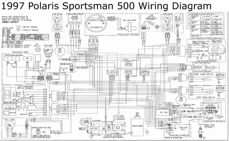


Polaris Sportsman 500 Ignition Wiring Diagram – Complete Layout: A Comprehensive Guide
The Polaris Sportsman 500 is a legendary ATV, known for its ruggedness and reliability. However, like any machine, electrical issues can arise. One of the most crucial components for a properly functioning Sportsman 500 is the ignition system. Understanding the ignition wiring diagram is paramount for troubleshooting, repairs, and modifications. This article provides a complete layout of the Polaris Sportsman 500 ignition wiring diagram, ensuring you can confidently navigate and maintain your ATV’s electrical system.
Understanding the Importance of the Ignition System
The ignition system is the heart of your Sportsman 500’s engine, responsible for generating the spark that ignites the air-fuel mixture within the cylinders. A malfunctioning ignition system can lead to a variety of problems, including:
- No spark: The engine won’t start.
- Weak spark: Difficult starting, misfires, and poor performance.
- Intermittent starting: The engine starts and stalls randomly.
- Reduced fuel efficiency: Incomplete combustion leads to wasted fuel.
A clear understanding of the wiring diagram allows you to diagnose and resolve these issues effectively.
Key Components of the Polaris Sportsman 500 Ignition System
Before diving into the diagram, it’s vital to familiarize yourself with the primary components of the ignition system. These include:
- CDI (Capacitor Discharge Ignition) Module: This is the brain of the ignition system, controlling the timing and delivery of the spark.
- Stator: Generates the electrical power for the ignition system.
- Flywheel: Contains magnets that interact with the stator to produce electricity.
- Ignition Coil: Steps up the voltage from the CDI module to generate the high voltage needed for the spark plugs.
- Spark Plugs: Generate the spark that ignites the air-fuel mixture in the engine.
- Wiring Harness: The network of wires that connects all the components.
- Ignition Switch: Controls the flow of electricity to the system.
- Kill Switch: Immediately cuts power to the ignition system for safety.
- Pickup Coil (Pulse Coil): Senses the crankshaft position and sends a signal to the CDI module to trigger the spark.
Decoding the Polaris Sportsman 500 Ignition Wiring Diagram
The wiring diagram is a schematic representation of the electrical system. It uses symbols and colors to indicate the connections between different components. Here’s a breakdown of how to interpret the diagram:
- Wire Colors: Wires are typically color-coded to help you identify their function and destination. Common colors include:
- Red: Positive (+) power supply.
- Black: Ground (-).
- Yellow: Often associated with lighting circuits.
- White: Frequently used for charging systems.
- Blue: Can be used for various circuits, including lighting and ignition.
- Green: Commonly used for ground connections.
- Brown: Frequently used for accessory circuits.
- Symbols: Various symbols are used to represent components like resistors, capacitors, switches, and connectors.
- Connectors: The diagram will show how components connect to each other using connectors.
Note: Always consult the specific wiring diagram for your Sportsman 500 model year, as variations may exist. You can find detailed wiring diagrams in the service manual for your ATV, readily available online or from Polaris dealers.
Simplified Wiring Diagram Overview
While the complete diagram is complex, here’s a simplified overview of the key connections:
- Power Source: The ignition system receives power from the battery, routed through the ignition switch.
- Ignition Switch: When the ignition switch is turned on, it allows power to flow to the CDI module.
- CDI Module: The CDI module receives signals from the pickup coil and other sensors (e.g., kill switch).
- Stator and Flywheel: The stator, energized by the flywheel’s magnets, provides AC voltage to the CDI module.
- Pickup Coil: The pickup coil signals the CDI module when to fire the spark plugs.
- Ignition Coil: The CDI module sends a signal to the ignition coil, which steps up the voltage.
- Spark Plugs: The high voltage from the ignition coil is delivered to the spark plugs, creating the spark.
- Kill Switch: The kill switch provides a way to cut the power to the CDI module, stopping the spark.
Troubleshooting Common Ignition Problems Using the Wiring Diagram
The wiring diagram is your primary tool for diagnosing ignition system issues. Here’s how to use it for troubleshooting:
- No Spark:
- Check the battery: Ensure the battery is fully charged and providing sufficient voltage.
- Inspect the ignition switch: Verify that the switch is functioning correctly and providing power.
- Test the CDI module: Use a multimeter to test the CDI module’s input and output voltages.
- Examine the ignition coil: Check the coil’s resistance and ensure it’s receiving power.
- Verify the pickup coil: Test the pickup coil’s resistance and ensure it’s sending a signal to the CDI module.
- Inspect wiring: Look for damaged wires, loose connections, and corrosion.
- Weak Spark:
- Inspect spark plugs: Replace worn or fouled spark plugs.
- Test the ignition coil: Check for proper voltage output.
- Check wiring for shorts or poor connections: Inspect the wiring harness for damage.
- Intermittent Starting:
- Check all connections: Ensure all connections are secure and free of corrosion.
- Test the ignition switch: The switch may be failing intermittently.
- Inspect the CDI module: A faulty CDI module can cause intermittent issues.
Safety Precautions
- Disconnect the Battery: Always disconnect the negative (-) terminal of the battery before working on the electrical system.
- Work in a Well-Lit Area: Ensure adequate lighting for clear visibility.
- Use Proper Tools: Use insulated tools and a multimeter for testing.
- Consult the Service Manual: Always refer to the service manual for specific procedures and safety warnings.
- Be Patient: Electrical troubleshooting can be time-consuming. Take your time and work systematically.
Conclusion
Understanding the Polaris Sportsman 500 ignition wiring diagram is essential for maintaining and repairing your ATV’s ignition system. By familiarizing yourself with the components, decoding the diagram, and following the troubleshooting steps, you can effectively diagnose and resolve electrical problems. Remember to prioritize safety and always consult the service manual for specific instructions. With this knowledge, you can keep your Sportsman 500 running smoothly for years to come.
Frequently Asked Questions (FAQs)
Where can I find the wiring diagram for my Polaris Sportsman 500?
You can find the wiring diagram in the service manual for your specific Sportsman 500 model year. These manuals are often available for purchase online or from Polaris dealers. You may also find them through online forums and communities dedicated to Polaris ATVs.
What tools do I need to troubleshoot the ignition system?
You’ll need a multimeter, a set of screwdrivers, wire strippers, and possibly a spark plug tester. A wiring diagram is also essential.
Can a faulty CDI module damage other components?
Yes, a faulty CDI module can potentially damage other components, such as the ignition coil or even the stator, particularly if it’s sending incorrect voltage signals or causing a short circuit.
What should I do if I suspect a wiring problem?
Carefully inspect the wiring harness for any signs of damage, such as frayed wires, cracked insulation, or loose connections. Check for corrosion at the connectors. Use a multimeter to test for continuity and shorts. Replace any damaged wires or connectors.
Is it possible to modify the ignition system on my Sportsman 500?
Yes, it is possible to modify the ignition system. However, modifications can affect the engine’s performance and reliability. Consult with a qualified mechanic or experienced ATV enthusiast before making any modifications.
