Low battery
Battery level is below 20%. Connect charger soon.


Supermax Wiring Diagram: The Electrical Setup Explained Step-by-Step
Are you embarking on a project that involves electrical wiring, perhaps for a new appliance, a renovation, or even a full-house electrical overhaul? Understanding the underlying wiring diagrams is crucial for safety and functionality. This article delves into the intricacies of Supermax wiring diagrams, providing a comprehensive, step-by-step guide to help you navigate the electrical setup process. We’ll break down the components, explain the connections, and offer practical advice to ensure a safe and successful outcome.
What is a Supermax Wiring Diagram?
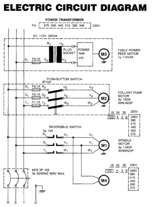
A Supermax wiring diagram, like any wiring diagram, is a visual representation of the electrical connections within a system. It acts as a roadmap, outlining the pathways for electricity to flow from the power source to the various components, such as outlets, lights, and appliances. The specific layout of a Supermax wiring diagram will depend on the specific application, but the fundamental principles remain consistent:
- Clear Visual Representation: Diagrams use symbols and lines to depict the connections.
- Component Identification: Each component (e.g., switches, outlets, circuit breakers) is clearly labeled.
- Wire Color Coding: Standardized color codes are used to identify different types of wires (e.g., black for hot wires, white for neutral, green/bare copper for ground).
- Step-by-Step Instructions: Diagrams often incorporate numerical sequences or notes to indicate the order of connections.
Understanding the Key Components in a Supermax Wiring Diagram
Before diving into the steps, let’s familiarize ourselves with the essential components typically found in a Supermax wiring setup:
- Power Source: This is the origin of the electricity, usually a circuit breaker panel or a connection to the existing electrical grid.
- Circuit Breakers: These safety devices protect the circuit from overcurrents and short circuits, acting as an automatic switch.
- Wiring: Cables and wires that conduct electricity throughout the system. Common types include:
- Hot (Live) Wire: Carries the electrical current from the power source. Typically black or red (in some cases).
- Neutral Wire: Provides a return path for the electrical current. Typically white.
- Ground Wire: Provides a safe path for electricity in case of a fault, preventing electric shock. Usually green or bare copper.
- Switches: Devices used to control the flow of electricity to lights, outlets, or other components.
- Outlets (Receptacles): Points where electrical devices are connected to the power source.
- Lights (Fixtures): The devices that convert electrical energy into light.
- Junction Boxes: Enclosures used to contain wire connections, protecting them from damage and ensuring safety.
Step-by-Step Guide to Interpreting and Following a Supermax Wiring Diagram
Following a Supermax wiring diagram requires careful attention to detail and a commitment to safety. Here’s a step-by-step approach:
- Safety First: De-energize the Circuit: Crucially, before you begin any wiring work, turn off the circuit breaker that controls the circuit you’ll be working on. Use a voltage tester to confirm that the power is off.
- Study the Diagram: Carefully examine the diagram. Identify all the components, their locations, and the connections between them. Pay close attention to wire colors and the numbered sequences.
- Gather Your Materials: Ensure you have all the necessary components, including wires, connectors, switches, outlets, junction boxes, and tools (wire strippers, wire connectors, screwdrivers, etc.).
- Run the Wires: Route the wires through the walls, ceilings, or wherever the diagram indicates. Ensure wires are secured and protected.
- Connect the Wires: This is where the diagram becomes your guide.
- Strip the wire ends: Use wire strippers to remove the insulation from the wire ends, exposing the conductors.
- Make the connections: Using wire connectors (wire nuts, crimp connectors), connect the wires according to the diagram. Be sure to make secure and reliable connections.
- Color Coding: Adhere strictly to the wire color code. Connect black (hot) wires to the correct terminals, white (neutral) wires to the neutral terminals, and green/bare copper (ground) wires to the ground terminals.
- Install Switches and Outlets: Mount the switches and outlets in their designated locations, connecting the wires according to the diagram.
- Test the Connections: After all connections are made, double-check them to ensure they are secure and correct.
- Restore Power: Once you’re confident in the wiring, restore power to the circuit by turning the circuit breaker back on.
- Test the Circuit: Test the functionality of the lights, outlets, and other components to verify that the wiring is working correctly.
Important Considerations and Safety Tips
- Always Consult Local Codes: Electrical codes vary by location. Ensure your wiring complies with all applicable local codes and regulations.
- Use Proper Tools: Employ the correct tools for the job, including wire strippers, screwdrivers, and a voltage tester.
- Avoid Overloading Circuits: Never overload a circuit by connecting too many devices. This can cause the circuit breaker to trip or, worse, lead to a fire.
- Hire a Qualified Electrician: If you are unsure about any aspect of the wiring process, or if the project is complex, consult a qualified and licensed electrician. Electrical work can be dangerous if not done correctly.
- Label Your Circuits: Clearly label all circuit breakers in your panel to identify which circuits they control.
FAQs About Supermax Wiring Diagrams
Here are some frequently asked questions about Supermax wiring diagrams:
What is the difference between a wiring diagram and a schematic diagram?
- A wiring diagram focuses on the physical layout and connection points of the components, while a schematic diagram represents the electrical circuit in a simplified, symbolic form, emphasizing the electrical flow.
What if I’m missing a wire color code in my wiring diagram?
- Always consult your local electrical codes. If the diagram is unclear, seek guidance from a qualified electrician. Never make assumptions about wire colors.
Can I use a standard diagram for any electrical project?
- No, the wiring diagram must match the specific project. It is important to use the wiring diagram that is designed for the electrical system you are building.
What should I do if I make a mistake while wiring?
- Immediately turn off the circuit breaker and disconnect the wires. Carefully review the wiring diagram and correct the mistake. If you are unsure, consult a qualified electrician.
Where can I find Supermax wiring diagrams?
- Supermax wiring diagrams are typically included with the product documentation for appliances, fixtures, or systems. You may also find them online, or you can consult with an electrician.
Conclusion
Understanding and correctly implementing a Supermax wiring diagram is fundamental to a safe and functional electrical setup. By following the step-by-step guide, paying attention to safety precautions, and consulting with professionals when needed, you can successfully navigate the complexities of electrical wiring. Remember to prioritize safety, always turn off the power before working, and adhere to all local electrical codes. Good luck with your project!
