Low battery
Battery level is below 20%. Connect charger soon.


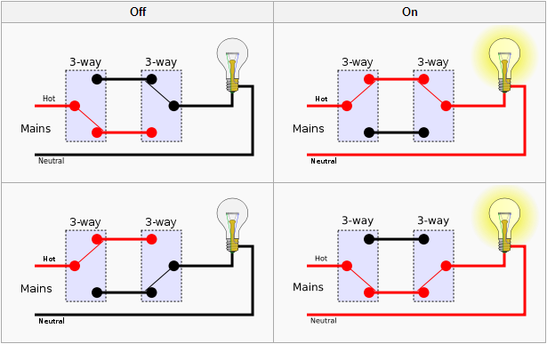
Three-Way Switch Diagrams: The Simple Trick Electricians Don’t Want You To Miss
Do you find yourself wrestling with the wiring for three-way switches, endlessly consulting diagrams that seem more complex than the task itself? You’re not alone. Three-way switches, allowing you to control a light from two different locations, are a common feature in homes, but the wiring can appear daunting. While professional electricians are adept at this, mastering the basics yourself can save you money and give you a satisfying sense of accomplishment. This article breaks down three-way switch diagrams, revealing a simple trick that simplifies the process and demystifies the wiring.
Understanding the Basics of Three-Way Switches
Before diving into the “secret,” it’s crucial to understand the core components and functionality of a three-way switch system. Unlike a standard on/off switch, a three-way switch doesn’t simply make or break a single circuit. Instead, it acts as a diverter, routing the electrical current along different paths.
- What they do: Allow you to control a single light fixture from two separate switch locations.
- How they work: Two switches are wired together using “traveler wires.” These wires act as the communication link between the switches, constantly shifting the power flow.
- Key Components:
- Two three-way switches
- A light fixture (or other electrical load)
- Wiring (typically 14/3 or 12/3 for residential applications, including a ground wire)
- Junction boxes to house the wiring connections
The Simple Trick: Visualizing the Traveler Wires
The often-overlooked key to understanding three-way switch diagrams lies in visualizing the traveler wires. These are the wires that connect the two three-way switches, and they are the core of the system’s operation. The simple trick? Think of the traveler wires as a constantly changing path for electricity.
- Focus on the Traveler Wires: Don’t get bogged down in the specifics of each switch; instead, trace the flow of current through the traveler wires.
- Imagine the Switch’s Internal Structure: Visualize the internal mechanisms of the switch, understanding that it’s essentially a “toggle” that directs the current to one traveler wire or the other.
- The Power Source and Load: Remember the power source (typically the breaker panel) and the light fixture (the load) are the start and end points. The switches and the traveler wires form the pathway in between.
Decoding Common Three-Way Switch Diagram Configurations
There are several common wiring configurations for three-way switches. Understanding these, along with the visualization trick, will make the process far easier.
- Power to the Light Fixture: In this configuration, the power source feeds directly to the light fixture, and then the wiring runs to the switches.
- Advantage: Simpler wiring at the switch locations.
- Disadvantage: Requires running wires to the light fixture first.
- Power to the First Switch: The power source feeds into the first switch, and the wiring then runs to the second switch and the light fixture.
- Advantage: Can be easier to wire if the power source is readily available at one switch location.
- Disadvantage: Requires running more wires between the switches.
- Power to the Second Switch: This configuration is similar to the “Power to the First Switch” setup, with the power source connected to the second switch.
- Advantage: Can be easier to wire if the power source is readily available at one switch location.
- Disadvantage: Requires running more wires between the switches.
Key Wiring Considerations (Regardless of Configuration):
- Neutral Wire: Typically, the neutral wire connects directly to the light fixture.
- Ground Wire: Always connect the ground wire to the ground terminals in each junction box.
- Proper Wire Connections: Use wire connectors (wire nuts) to securely connect wires of the same color and gauge.
- Safety First: Always turn off the power at the circuit breaker before working on any electrical wiring. Use a non-contact voltage tester to verify that the wires are de-energized.
- Labeling is Key: Label the wires at each junction box during the disconnection phase of your project. This will make re-wiring and troubleshooting much easier.
Essential Tools and Materials
Before embarking on your three-way switch project, ensure you have the necessary tools and materials:
- Three-way switches (matching the type you’re replacing)
- Wiring (14/3 or 12/3 with ground, depending on your circuit’s amperage)
- Wire strippers/cutters
- Screwdrivers (Phillips and flathead)
- Wire connectors (wire nuts)
- Electrical tape
- Non-contact voltage tester
- Multimeter (for testing continuity and voltage)
- Junction boxes (if needed)
Troubleshooting Common Issues
Even with careful planning, you might encounter some issues. Here are some common problems and their solutions:
- Light Doesn’t Turn On:
- Check the circuit breaker.
- Verify all wire connections are secure.
- Ensure the light bulb is good.
- Test the voltage at the light fixture and the switches.
- Check the traveler wires for proper connections.
- Light Stays On or Off:
- Incorrect wiring, especially involving the traveler wires. Double-check the diagram and your connections.
- A faulty switch. Replace the switch.
- Flickering Lights:
- Loose wire connections. Tighten all connections.
- Overloaded circuit. Reduce the load on the circuit.
Conclusion: Mastering the Three-Way Switch
By understanding the fundamental principles, visualizing the traveler wires, and utilizing the correct diagrams, you can confidently tackle three-way switch wiring. While the initial diagrams may seem complex, the simple trick of focusing on the flow of current through the traveler wires makes the process significantly more manageable. Take your time, prioritize safety, and don’t hesitate to consult additional resources or a qualified electrician if you feel uncomfortable. With practice and patience, you can master this common electrical task and enjoy the convenience of controlling your lights from multiple locations.
FAQs
What is the difference between a three-way switch and a four-way switch?
- A three-way switch allows control from two locations. A four-way switch allows control from three or more locations. Four-way switches are wired between two three-way switches.
Can I use standard on/off switches instead of three-way switches?
- No, standard on/off switches will not work in a three-way switch circuit. They lack the necessary terminals and internal mechanisms to divert the current.
What size wire should I use for three-way switches?
- The wire size depends on the circuit’s amperage. For most residential lighting circuits (15 or 20 amps), 14-gauge wire is typically used. However, always consult local electrical codes and the rating of your circuit breaker.
What if I accidentally disconnect the wires and don’t know where they go?
- Carefully label all wires before disconnecting them. If you’ve already disconnected them without labeling, use a multimeter to test for continuity to determine which wires are connected to each other. Be sure to turn off the power at the breaker before doing so.
Is it safe to work with electrical wiring myself?
- Working with electricity can be dangerous. Always turn off the power at the circuit breaker before starting any electrical work. If you are not comfortable with electrical wiring, or if you are unsure about any step, it is best to consult a qualified electrician.
